4.8. Advanced
4.8.1. Annotations
MQC allows you to annotate the quality of the quality properties and artifacts in your project. This functionality will enable you to add a description to justify the observed quality for the duration of your project. This description/comment lets other users know why a certain quality property is performing a certain way and leads to a more transparent documentation.
You could use annotations to document deviations from expected values for special, real-world cases. Additionally, you can use annotations to change the quality value or bin if they need to be treated differently than the one calculated.
See When not to use Annotations to learn about use cases that should be treated by other MQC features rather than using annotations.
Use annotations sparingly to describe or justify the quality of certain quality properties and artifacts. Modify the quality value or bin only if necessary.
4.8.1.1. Create and Edit Annotations
Annotations can be configured in the dialog.
To create a new annotation click Create at the top right of the
dialog.
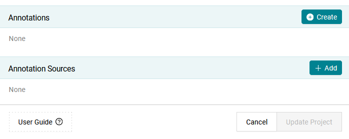
Figure 4.53 Create a new annotation by clicking on the Create button.
This opens a form that has to be filled out by the user.
In case of marked certain artifacts or quality properties from the KPIs,
or an element from the main visualization, the marked elements are pre-selected
respectively in the Annotations dialog and in the Create Annotation
dialog. If you want to remove this pre-selection, simply uncheck the Show marked only
check box at the top of the Annotations dialog.
If an element was marked in the main visualization, the
Valid From, Valid To and Bin fields will also be filled automatically
with the corresponding information.
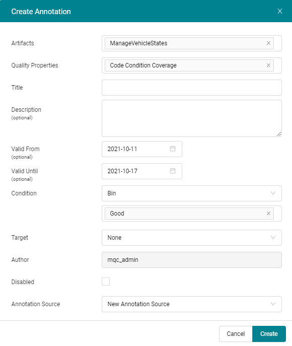
Figure 4.54 Prefilled form to create an annotation after selecting a quality tile in the Quality Status matrix.
When no quality properties or artifacts were selected, the form is empty and has to be filled out completely.
The following fields are available to define an annotation.
Artifacts: (mandatory)
Select one or more artifacts this annotation should be applied to.
Quality Properties: (mandatory)
Select one or more quality properties this annotation should be applied to.
Title: (mandatory)
Add a caption or a title to identify the annotation easily or to provide a quick overview of the annotation.
Description: (optional)
Add a more detailed justification or description of the annotation.
Valid From: (optional)
Select the start date from which the annotation is active. If left empty MQC treats the annotation as active from the start date of the project.
Valid To: (optional)
Select the end date until which the annotation is active. If left empty MQC treats the annotation as active until the end date of the project.
Condition:
Define the qualifying condition based on which the underlying quality value or bin would be changed.
Target:
Define the target quality value or bin you would like to annotate when the condition defined above is true.
Disabled:
Enable or disable an annotation. Disabled annotations are not applied but remain in the project and can be enabled at any point in time.
Annotation Source: (mandatory)
Assign the annotation to annotation source. By default a New Annotation Source with the name NewAnnotationSource.yml will be added and the annotation will be stored in this source. Later NewAnnotationSource.yml can be saved (see Managing Configurations).
You can use different combinations of qualifying conditions and desired target values for an annotation. For example:
If you want to change a quality bin from Bad to Acceptable, set the Condition type to Bin and select the quality bin
Bad. Then set the Target type to Bin and select the quality binAcceptable.If a quality bin is too broad you could use the Quality condition instead. Set the Condition type to Quality and select a range between
10to15. Then set the Target type to Bin and select the quality binAcceptable.If the target bin makes the quality too high and you would like to specify it directly, then set the Target type to Quality and the quality value to
25.Finally, you can also define the condition as bin and target as value. Set the Condition type to Bin and select the quality bin
Bad. Then set the Target type to Quality and the quality value to25.
If the target is a bin then the underlying quality value is also changed and vice versa. The respective values are chosen from the bin configuration (see Quality Bins).
Once annotations are created, they can be seen in the Annotation dialog.
If any field is invalid, it is marked in red, the annotation is grayed out,
and the annotation cannot be applied to the project, for example, if the
Valid From or Valid To dates are outside the timeline of the project.
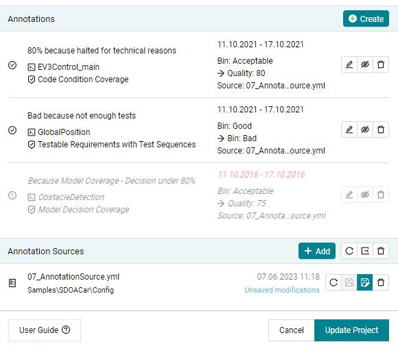
Figure 4.55 Annotation dialog after annotation is created.
Each annotation can be edited in the Edit Annotation dialog which is the same
as the Add Annotation (Figure 4.54).
Click Update to apply the changes.
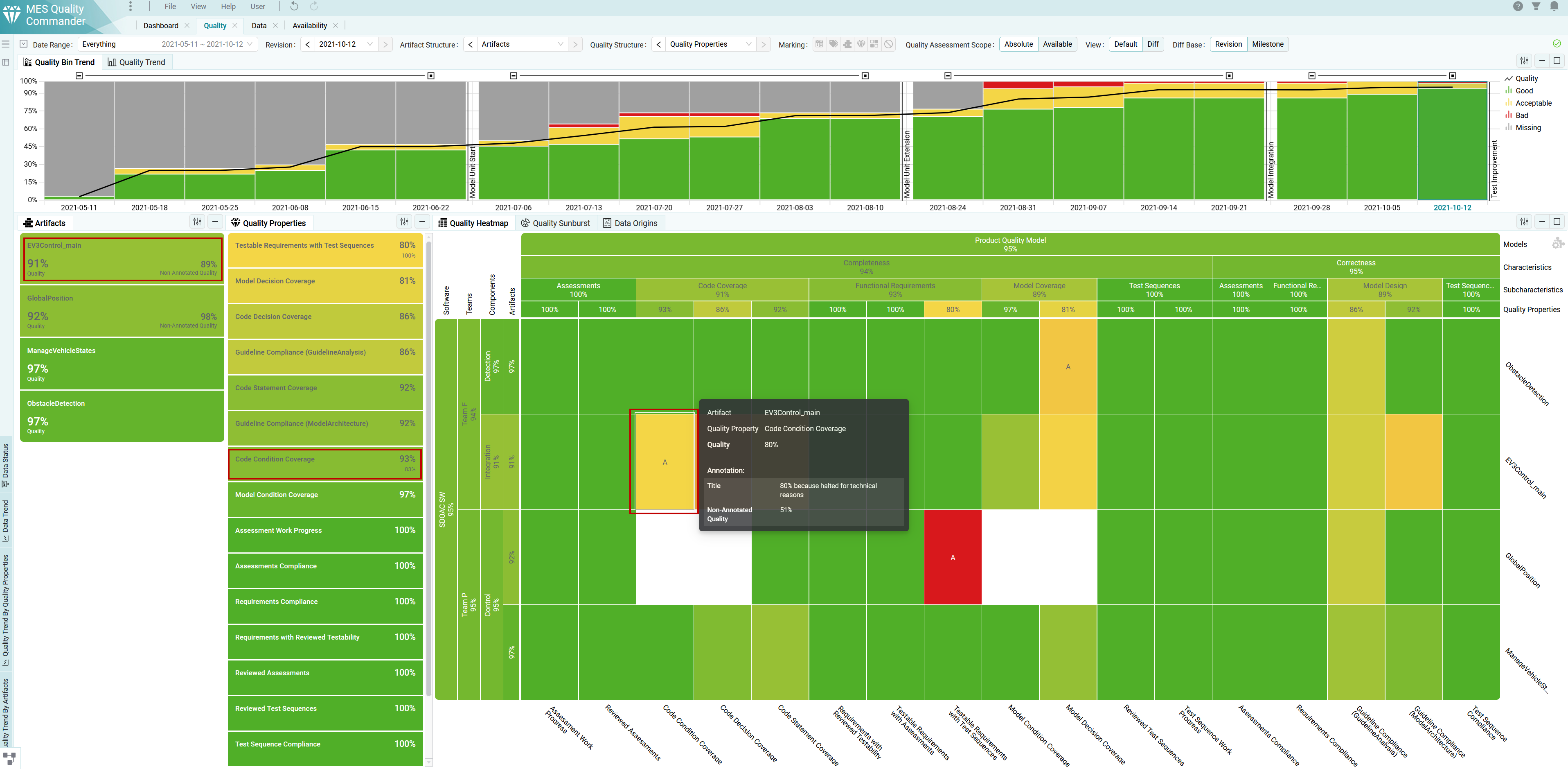
Figure 4.56 Quality status page with annotations applied to your project.
Non-Annotated Quality stands for the quality value before annotation
was applied.
MQC displays applied annotations:
as an “A”-Indicator inside the Heatmap (cells with annotated quality show an “A” in addition)
within the Tooltip for an annotated quality point (title, description and the change of quality, if defined, will be displayed)
in the KPIs (the KPI value shows the annotated quality, the comparative value shows the “Non-Annotated Quality”).
4.8.1.2. When not to use Annotations
Annotations should be used to justify very specific and local deviations, especially if such a deviation applies to a specific point in time only. Particularly, annotations should not be used to cover one of the following cases.
If you don’t expect any data measure and don’t want MQC to calculate quality for a particular artifact respectively model, this artifact should be excluded from the project using a proper Project Structure configuration (see Artifact Structures).
If you don’t want to track a certain quality for a particular artifact, you should use context categories to exclude the underlying data for that particular artifact (see Context Categories). If data is excluded for an artifact, also the quality resulting out of this data will not be calculated for that artifact.
If the measured data values, that are loaded into MQC, objectively imply a certain quality, but the resulting quality value shown in MQC does not reflect that, the corresponding quality measurement function should be adapted accordingly (see Quality Properties).
Define targets for quality values (see Target Values) rather than using annotations as justification. By using targets, you may specify that the relative quality is 100% if the configured target was reached or even exceeded, even if the calculated absolute quality does not reflect that at all, but meets the expectations for that point in time.
4.8.2. Artifact Mapping Patterns
Artifact Mapping allows you to adapt artifact names as they are used by data sources to your needs. Especially if different data sources use different denominations for the same artifact, Artifact Mapping may be used to define a common artifact name. All imported measure values collected by the data sources are automatically assigned to the new artifact name.
Artifacts:
- Name: ObstacleDetection
  Paths:
  - ObstacleDetection
  - EV3Control_demo_ec/VehicleManager/ObstacleDetection
  - ObstacleDetection_demo_ec
  - Obstacledetection_demo_ec
  - ObstacleDetection_demo_ec/ObstacleDetection
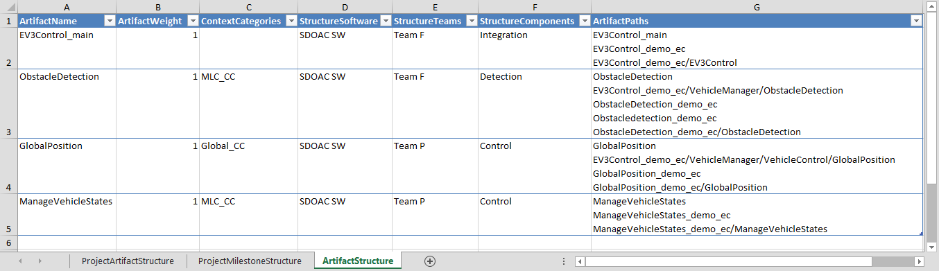
Figure 4.57 Different artifact paths are mapped to a common artifact name in Excel using the “Artifact Structure” sheet
In Excel, as shown in Figure 4.57, in the ArtifactPaths column
of the Artifact Structure sheet, all artifact paths with same artifact name are
listed separated by line break or comma characters.
In case the same base measures were provided for different artifact paths for the same revision and are now mapped to a common artifact name, MQC only uses the most recent of these base measures to calculate quality for the artifact.
Artifact Mapping configuration is part of the Project Structure source (see Project Structure).
Additionally, it is possible to map artifacts in case you do not have a project structure configuration yet. To map artifact paths to artifact names, you need to define regular expression patterns.
In menu you can define Artifact Mapping Pattern from
the dialog Create Artifact Mapping Pattern. Here, you can define the Search RegEx
and Replace values and the effective result can also be directly seen on the pageable list.
For example in Figure 4.58,
the pattern is defined as: Search RegEx: ^(.*)_demo_.*$ , Replace: $1, which means the
artifact name is the substring of artifact path before _demo_.
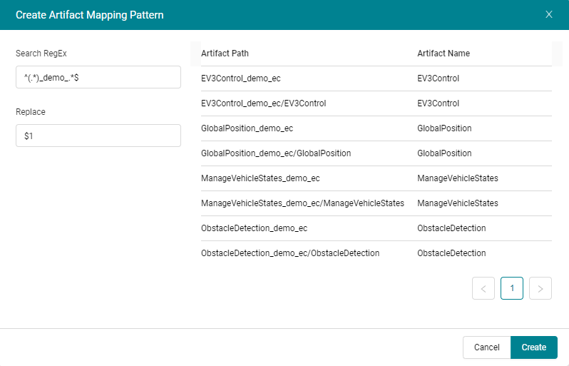
Figure 4.58 Define new pattern for artifact mapping
It is possible to define more than one pattern can be defined. However, the first matching pattern from the list will be applied to the artifact path. The order of the patterns can be changed in the list. The result of these patterns are also present in the export of artifact structure.
4.8.3. Quality Bins
MQC allows to adapt the Quality Bin Configuration via the dialog. Bins are used to group quality aspects of a project, i.e. a quality property per artifact for a certain point in time (revision), into categories (see Bins). As per default, MQC uses the calculated quality value to assign a quality property to a quality bin.
You can define project specific quality bins by assigning a Color, Name, and
an Upper quality boundary (see Figure 4.59). After creating/editing
a quality bin it will be added to the list of already existing quality bins.
There is no limit of quality bins you can configure for your project, but be
aware there can be only one quality bin for the same upper quality boundary
value.
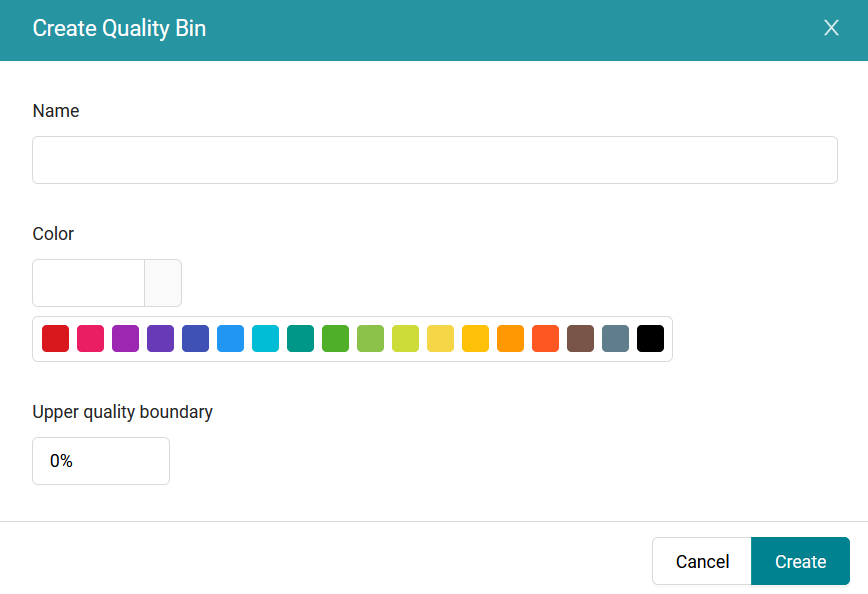
Figure 4.59 Dialog to add or edit Quality Bin
With the given upper quality boundary values MQC is able to define the value ranges for the configured quality bins. Quality values are between 0 % and 100 %. Therefore it is required to define an upper quality boundary of 100 % for the highest quality bin. Then MQC automatically takes the upper quality boundary of the next quality bin as the lower boundary (where the quality bins will be automatically sorted according to the given quality boundary values).
For the default configuration the resulting value ranges are as follows:
Good (green): ]80%, 100%]
Acceptable (yellow): ]20%, 80%]
Bad (red): [0%, 20%]